Adaptive optics (AO) is a cornerstone technology for modern astronomy because it enables ground-based telescopes to compensate for atmospheric turbulence in real time and approach their diffraction limit. As next-generation large telescopes such as the Giant Magellan Telescope (GMT) move towards operation, wavefront sensor requirements are becoming increasingly demanding. Sensors must operate at frame rates of up to several kilohertz, offer high sensitivity to elongated laser guide stars, and remain reliable, compact, and practical to manufacture.
The new Andor CB2 1.7 Megapixels for WFS from Oxford Instruments – First Light Imaging has no protective front window. It was developed for the GMT laser tomography adaptive optics (LTAO) system and enables a relay-optics-free Shack-Hartmann wavefront sensor.
Adaptive optics for large telescopes
How adaptive optics works
Adaptive optics compensates in real time for optical wavefront distortions introduced by atmospheric turbulence or optical imperfections. A typical system consists of a wavefront sensor, a real-time controller, and a deformable mirror.
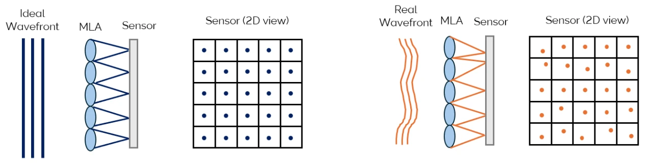
The Shack-Hartmann sensor uses a microlens array (MLA) to divide the incoming beam into many sub-apertures. Each microlens focuses light onto a detector to produce a spot pattern. A flat wavefront produces spots at known reference positions, while a distorted wavefront shifts them. The sensor reconstructs the wavefront from these displacements, and the controller commands the deformable mirror to apply the opposite distortion. This process is repeated hundreds to thousands of times per second.
Why wavefront sensing is critical
For observatories such as GMT, the Thirty Meter Telescope (TMT), and the future Extremely Large Telescope (ELT), adaptive optics is essential for exoplanet imaging, stellar population studies, and observations of distant galaxies. Wavefront-sensor performance directly affects final image quality.
Wavefront sensing for GMT laser tomography adaptive optics
The LTAO mode planned for GMT does not rely on a single reference star. Six powerful lasers tuned to the sodium layer approximately 90 km above Earth create a constellation of artificial laser guide stars around the science target. Measuring the distortions from all six directions makes it possible to reconstruct a three-dimensional map of atmospheric turbulence.
GMT-LTAO employs six Shack-Hartmann wavefront sensors, one for each laser guide star. Each sensor samples the 25.4 m telescope pupil with a 60 × 60 sub-aperture grid. The resulting information commands the secondary adaptive mirror hundreds of times per second and restores near-diffraction-limited image quality.
GMT innovation: relay-optics-free Shack-Hartmann wavefront sensing
Traditional wavefront sensors employ relay optics after the microlens array to re-image the spot pattern onto a detector. Relay optics add alignment complexity, optical losses, volume, weight, and long-term-instability challenges. Because every LTAO instrument requires six wavefront-sensing channels, even modest simplifications can significantly affect the overall observatory architecture.
The work of Ogane et al. presents a relay-optics-free Shack-Hartmann wavefront sensor in which a custom microlens array is positioned directly in front of a high-speed CMOS detector. Eliminating the relay optics reduces the number of optical components, improves photon throughput, and enables a more compact and robust architecture while preserving the field of view and sampling needed for elongated laser-guide-star images.
| Conventional approach | Relay-optics-free approach |
|---|---|
| Multiple relay lenses | No relay imaging optics |
| Higher alignment burden | Simplified architecture |
| Additional throughput loss | Improved photon efficiency |
| Larger packaging volume | Compact footprint |
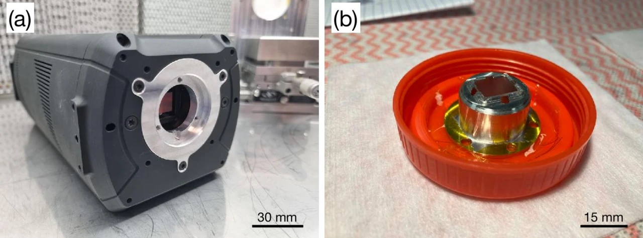
The GMT prototype replaces the relay-optics chain by positioning a custom double-sided microlens array directly in front of a CB2 1.7 Megapixels for WFS global-shutter CMOS sensor. The array has a very short 0.105 mm back focal distance, enabling spot formation directly on the detector. The windowless CB2 design was crucial; a custom sealed assembly with dry-nitrogen purging for low-temperature operation replaced the protective window.
Benefits of a windowless camera for WFS
Most scientific cameras have a protective glass window in front of the sensor. Although it protects the detector and seals the housing, it can introduce undesirable effects in a wavefront sensor.
No spurious reflections and ghost images
Air-glass interfaces generate multiple reflections that can superimpose ghost images on the Shack-Hartmann spots in a compact focal instrument. These artefacts are particularly detrimental to already elongated laser-guide-star spots. With no window, these artefacts do not arise and the images are sharper.
No interference
A plane-parallel window acts as a Fabry–Pérot etalon. With a coherent or quasi-monochromatic source such as a 589 nm sodium laser, interference fringes can disrupt centroid estimation. A windowless camera does not suffer from this effect.
Flexible working distance
A window adds an optical path that constrains the mechanical design of the camera/WFS interface. A windowless design facilitates tight mechanical integration into compact adaptive-optics systems.
Prototype validation
Experimental validation demonstrated successful alignment and operation of the integrated detector–microlens-array assembly. The measured spot spacing matched the design target of 14 pixels per sub-aperture. Only 0.02% of pixels were inoperable, so detector cosmetics comfortably met the system requirements.
A spatial variation in spot size was observed across the detector and attributed to a small residual tilt between the microlens-array and detector planes. Performance nevertheless remained compatible with GMT-LTAO requirements and validated the feasibility of the relay-optics-free concept. The work also established practical assembly, alignment, sealing, and dry-nitrogen-purging procedures.
Implications for future adaptive-optics systems
Reducing subsystem complexity is increasingly important as instrument counts, detector channels, and maintenance demands grow. The GMT prototype shows that direct microlens-array-to-detector coupling can remove a significant optical subsystem without compromising performance. Benefits include higher throughput, reduced mass and volume, fewer alignment-sensitive components, and potentially improved long-term reliability.
Low-noise, high-speed sCMOS cameras such as the Andor CB2 1.7 Megapixels for WFS enable compact wavefront-sensor architectures that were previously impractical.
Conclusion
The GMT-LTAO prototype demonstrates a robust, relay-optics-free Shack-Hartmann wavefront-sensor architecture. Direct integration of a custom microlens array with a modern high-speed, low-noise CMOS detector provides the compactness and simplicity needed for large-scale adaptive-optics deployment while meeting fundamental wavefront-sensing performance targets.
Download the CB2 for WFS technical specification (PDF)
Source: Ogane et al., Prototyping results of the Relay-optics-free Shack-Hartmann wavefront sensor for the GMT laser tomographic adaptive optics, JATIS, submitted, 2026.


