The new Andor CB2 scientific camera variant without a protective window enabled the development of a compact Shack-Hartmann wavefront sensor without relay optics. Developed for the Giant Magellan Telescope, the solution reduces optical losses, unwanted reflections, and interference while allowing the microlens array to be positioned directly in front of the sensor.
Adaptive optics (AO) is one of the key technologies of modern astronomy. It enables ground-based telescopes to compensate for atmospheric turbulence in real time and approach their diffraction limit.
With the arrival of a new generation of large telescopes such as the Giant Magellan Telescope (GMT), wavefront-sensor requirements are also increasing. These sensors must operate at frame rates of several kilohertz while providing high sensitivity to elongated laser guide star (LGS) images.
Adaptive-optics systems must also deliver greater correction accuracy while remaining reliable, compact, and practical to manufacture.
This application note summarises the principles of adaptive optics and presents a new relay-optics-free Shack-Hartmann wavefront-sensor design based on the CB2 1.7 Megapixels for WFS camera. This new Oxford Instruments CB2 variant has no protective front window and was developed for the GMT laser tomography adaptive optics (LTAO) system.
Adaptive optics: a key technology for large telescopes
How adaptive optics works
Adaptive optics compensates in real time for optical-wavefront distortions introduced by atmospheric turbulence or imperfections in the optical system.
A typical adaptive-optics system consists of three main components:
- a wavefront sensor, such as a Shack-Hartmann sensor,
- a real-time controller,
- a deformable mirror.
The Shack-Hartmann sensor uses a microlens array (MLA) to divide the incoming beam into many sub-apertures. Each microlens focuses light onto a detector and creates a corresponding light spot.
For a perfectly flat wavefront, the spots appear at known reference positions. When the wavefront is distorted, its local slopes shift the individual spots relative to those positions.
The system reconstructs the shape of the incoming wavefront from these displacements. The controller then calculates the opposite distortion and commands the deformable mirror to adjust its surface.
This process is repeated hundreds to thousands of times per second, restoring image quality and bringing the system close to diffraction-limited performance.
Shack-Hartmann wavefront sensors are widely used in astronomical adaptive optics because they provide a direct, robust, and high-speed measurement of local wavefront slopes.
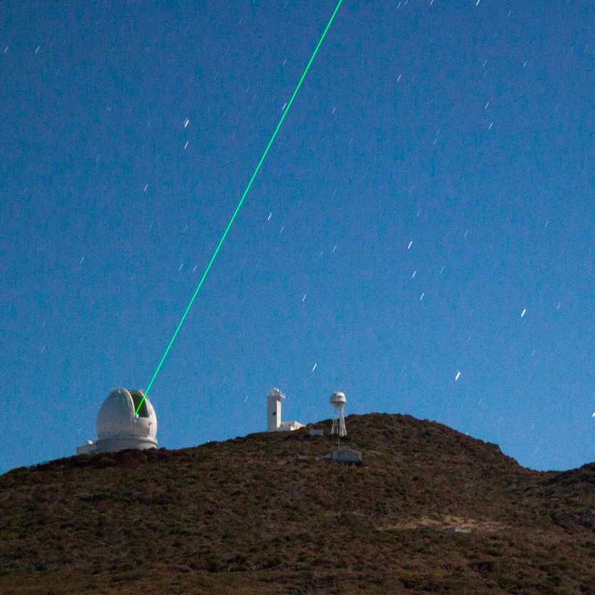
Figure 1: A ground-based observatory using a laser guide star to compensate for atmospheric turbulence.
Why adaptive optics and wavefront sensing are critical for large telescopes
For observatories using telescopes such as GMT, the Thirty Meter Telescope (TMT), and the future Extremely Large Telescope (ELT), adaptive optics is essential for scientific tasks including:
- exoplanet imaging,
- stellar-population studies,
- observations of distant galaxies.
Atmospheric turbulence distorts incoming wavefronts from astronomical objects and reduces spatial resolution and sensitivity.
Adaptive-optics systems therefore measure these distortions with wavefront sensors and correct them using deformable mirrors that can be updated hundreds to thousands of times per second.
Wavefront-sensor performance thus directly affects final image quality.
Wavefront sensing for GMT laser tomography adaptive optics
The Giant Magellan Telescope will rely heavily on adaptive optics to achieve its scientific goals, including exoplanet characterisation, stellar-population studies, and high-resolution spectroscopy.
One of its planned operating modes is laser tomography adaptive optics (LTAO).
Unlike systems that use a single reference star, LTAO uses powerful lasers tuned to the atmospheric sodium layer approximately 90 km above Earth to create six artificial stars.
These laser guide stars form a constellation of reference points around the observed object and provide several different views through the atmosphere.
By measuring the distortions seen by all six guide stars simultaneously, the system can reconstruct a three-dimensional map of atmospheric turbulence above the telescope.
This process, known as atmospheric tomography, determines at which altitudes the turbulence occurs and how individual atmospheric layers contribute to image degradation.
The GMT-LTAO system therefore uses six Shack-Hartmann wavefront sensors, one for each laser guide star.
Each sensor samples the telescope’s 25.4 m aperture with a 60 × 60 sub-aperture grid. The resulting data is used to control the adaptive secondary mirror hundreds of times per second.
GMT innovation: a relay-optics-free Shack-Hartmann wavefront sensor
Traditional wavefront sensors use a microlens array followed by relay optics that re-image the resulting spot pattern onto a detector.
This approach works, but relay optics introduce several disadvantages:
- more complex optical alignment,
- additional optical losses,
- greater size and weight,
- a risk of long-term instability.
Because the GMT LTAO system requires six separate wavefront-sensing channels, even a relatively small reduction in the size and complexity of each channel can significantly affect the overall system design.
The work of Ogane et al. describes a relay-optics-free Shack-Hartmann wavefront sensor in which a specially designed microlens array is positioned directly in front of a high-speed CMOS detector.
Removing the relay optics:
- reduces the number of optical elements,
- increases photon-throughput efficiency,
- enables a more compact design,
- improves wavefront-sensor robustness.
The required field of view and sampling of elongated laser-guide-star images are retained.
The main technical challenge shifts from the optical system to highly accurate mechanical alignment of the microlens array relative to the detector.
Comparison of approaches
| Conventional approach | Relay-optics-free approach |
|---|---|
| Several relay lenses | No imaging relay optics |
| Higher optical-alignment demands | Simplified design |
| Additional optical losses | Higher photon-throughput efficiency |
| Larger construction volume | Compact design |
The GMT prototype replaces the entire relay-optics assembly with a custom double-sided microlens array positioned directly in front of the global-shutter CMOS sensor in the CB2 1.7 Megapixels for WFS.
The microlens array has a very short back focal distance of 0.105 mm, allowing the light spots to form directly on the detector.
The windowless CB2 for WFS architecture was crucial to this configuration. The protective window was replaced by a custom sealed assembly with dry-nitrogen purging for low-temperature operation.
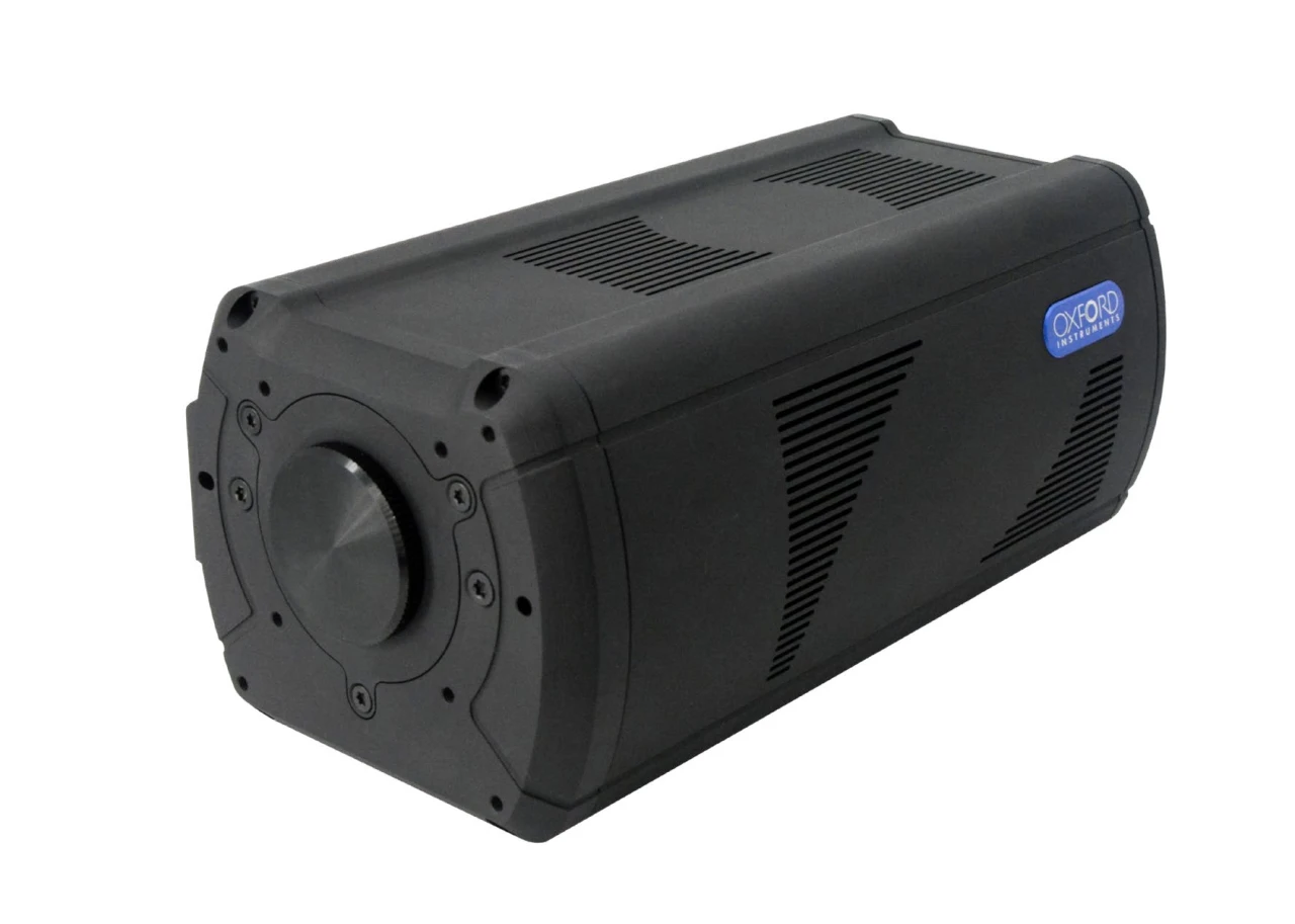
Figure 2: An Andor CB2 scientific camera. The windowless CB2 for WFS variant enables close coupling between the sensor and a microlens array or other downstream optics.
Benefits of a windowless camera for wavefront sensing
Most scientific cameras use a protective glass window made of BK7, fused silica, or anti-reflection-coated glass in front of the sensor.
The window protects the detector from mechanical damage and seals the camera body. In wavefront-sensing applications, however, it can also introduce undesirable optical effects.
A windowless design offers several key advantages.
No unwanted reflections or ghost images
Air-glass interfaces create multiple reflections that can produce unwanted images superimposed on Shack-Hartmann spots in the compact focal systems typical of wavefront sensors.
These artefacts are particularly problematic for laser guide stars, whose images are naturally elongated and sensitive to additional light contamination.
Removing the window eliminates this source of artefacts and enables sharper images.
No interference patterns
A plane-parallel window can act as a Fabry–Pérot etalon.
When a coherent or quasi-monochromatic source is used, such as a 589 nm sodium laser, interference fringes can appear in the image and complicate accurate centroid determination for individual light spots.
A windowless camera does not suffer from this interference, helping to improve image quality.
More flexible working distance
A protective window extends the optical path and constrains the mechanical arrangement of the interface between the camera and the wavefront sensor.
A windowless architecture allows downstream optics to be positioned closer to the sensor and simplifies integration into compact adaptive-optics systems.
Validation of the relay-optics-free wavefront-sensor prototype
Experimental tests confirmed successful alignment and operation of the integrated detector and microlens-array assembly.
The measured spot spacing matched the design value of 14 pixels per sub-aperture, indicating that spot-grid geometry is primarily determined by the manufacturing precision of the microlens array.
Detector quality comfortably met the system requirements: only 0.02% of pixels were inoperable.
A variation in light-spot size was observed across the sensor area and attributed to a small residual tilt between the microlens-array and detector planes.
Performance nevertheless remained compatible with GMT-LTAO requirements and confirmed the viability of the relay-optics-free concept.
The development also established practical procedures for:
- assembly,
- precise alignment,
- sealing,
- dry-nitrogen purging.
Implications for adaptive-optics systems at future observatories
Reducing subsystem complexity is increasingly important for the next generation of adaptive-optics systems as the number of instruments, detector channels, and maintenance requirements grows.
The GMT prototype shows that directly coupling the microlens array to the detector can remove a significant part of the optical system without compromising the required performance.
The main benefits include:
- higher optical throughput,
- lower weight,
- a smaller construction volume,
- fewer components sensitive to precise alignment,
- potentially greater long-term reliability.
Low-noise, high-speed sCMOS cameras such as the Oxford Instruments CB2 1.7 Megapixels for WFS enable compact wavefront sensors that were previously impractical to implement.
Such solutions can support the development of scalable adaptive-optics systems for the scientific goals of next-generation observatories.
Conclusion
The GMT-LTAO prototype demonstrates a robust relay-optics-free Shack-Hartmann wavefront-sensor design.
Direct coupling of a specially designed microlens array to a modern high-speed, low-noise CMOS detector provides a compact and simpler solution suitable for large-scale adaptive-optics systems while meeting the fundamental wavefront-sensing accuracy requirements.
Source
Ogane et al., Prototyping results of the Relay-optics-free Shack-Hartmann wavefront sensor for the GMT laser tomographic adaptive optics, JATIS, submitted, 2026.
Translated from the original: Oxford Instruments / Andor, Adaptive Optics for the Giant Magellan Telescope: A Relay-Optics-Free Wavefront Sensor Design Using the CB2 for WFS, 2026.


